Building Blocks of the M365
From the electronic perspective the M365 consists of 4 main parts and some additional components:
BLE-Module
- Located in the handlebar
- We can turn the scooter on, off, change eco/normal mode and turn off/on the lights
- it's connected with 2 Hall sensors in the Throttle and Brake Levers
- it has a beeper which is used when the ESC requests it to beep
- it has 4 white status leds, where the lowest LED can also be lit in green (when in eco mode)
- the processor has a BLE Radio built in, so all Apps connect with the ble module
- there's no schematics 😦
- the processor sits on a small pcb module, labeled ninebot and is a Nordic Semiconductor nRF51822 (Cortex-M0 with BLE)
- the 2 hall sensors are power with 5V, the output range is not from 0 to 5v (as usual with hall sensors...)
- the front led is powered with 6V and 180mA via a stepup converter from the 5V
- the connection to the rest of the scooter is a 4 wire cable, the pins are named
- P: "Power" - wired with the switch, it's actually handled by the esc, used to power on/off and single/doubleclick when powered on. The Switch connects P to G when pressed
- 5: like in 5 Volt - should manage to deliver ~500mA, but only when the scooter is powered on
- T: Data Bus - see Communication Details
- G: Ground
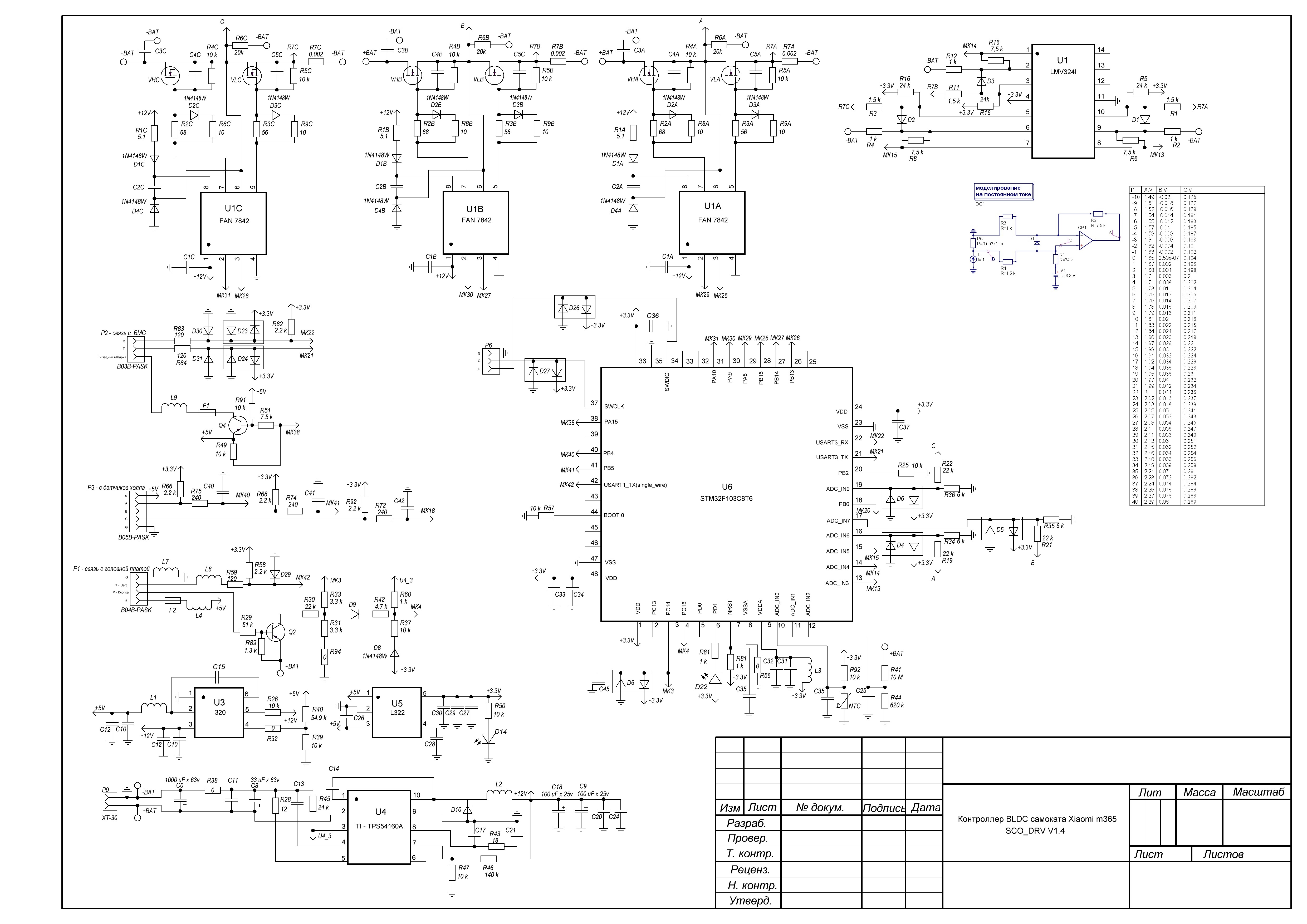
ESC-Module
- Connected with the motor, the motor Hall-Sensor, the BLE-module, the BMS-module and the backlight
- U6: Processor U6: STM32F103C8T6
- U4: TPS54160A: DC-DC Stepdown from Vbatt to 12V via AliExpress
- U3: TPS563200: DC-DC Stepdown from 12V to 5V via AliExpress
- U5: TPS78233: DC-DC Stepdown from 5V to 3.3V
- Schematics ESC (from source, latest version can be found here)
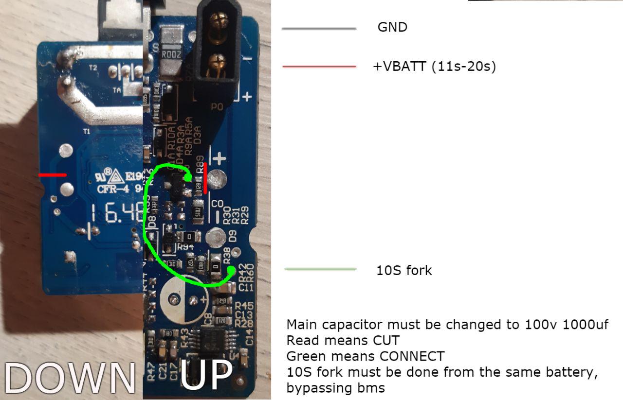
- Modification of ESC Power Supply
- TODO: connectors
mostly taken from https://github.com/etransport/ninebot-docs/wiki/M365ESC
BMS Module
- Processor: STM8L151K6T6
- BMS Chip: STM8L151K6T6
- Schematics BMS
- Source Code of v1.15
- Charging Current is limited to 2.499A
- Balancing is done automatically when the scooter was not used for a certain time and when there's a cell-voltage difference bigger than 30mV. So there's no need for leaving the scooter on or leaving it on the charger overnight
mostly taken from https://github.com/etransport/ninebot-docs/wiki/M365BMS